|
 |

|
|
|
|
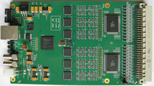
ASF48(P), ASF48sc and ASF48cfg
48-channel front-end card with Amplifiers, Shapers and FlashADCs
|
|
 |
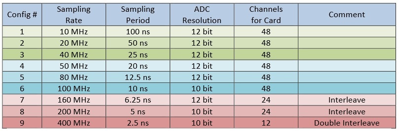
- FlashADC: .......................................12-Bit Octal-Channel ADS5282.
- Sampling Rate: ...............................65 MSPS.
- Sampling Period: ............................15.38 ns.
- Number of Channels: ......................48.
- Direct access to FlashADC inputs via additional connectors for a Mezzanine card with alternative amplifiers / shapers.
- Processing logic: ............................Spartan-6 XC6SLX45 FPGA.
- Triggering modes: ..........................Self, External, Special Functions.
- Event Time Stamp, resolution: .......10 ns.
- Event Time Stamp, duration: ..........24 hours.
- Card size: ......................................100 x 160 mm.
- Single power: .................................2.7 A @ 3.8 V.
- Target DAQ system: ........................CROS3.
- Target applications 1: ....................«POLFUSION»
(Figure 1. ASF48P, Plan View).
- Target applications 2: ....................«NEUTRINO-4»
(Figure 2. ASF48P with a Mezzanine card, Plan View).
- Detail information: ..........................HERE.
|
|
Execution option, focused on work with external trigger - ASF48sc
PRELIMINARY. A NEW MULTIMODE FRONT-END CARD - ASF48cfg
Target DAQ system: CROS3
|

|
|
Abstract - The procedure for increasing the amplitude resolution in the digital representation with asynchronous samples of signals with an unknown moment of their appearance is expounded.
1. Introduction
In the traditional path of recording the initial charge of a detector, a quasi-optimal filter is used from the point of view of the maximum amplitude resolution. Practically this is sufficient for a fixed implementation of the experiment. The digital representation of the samples of the output signal of the filter, if you want to know its maximum value, is simply costly and not exactly a reasonable solution. But this approach provides opportunities for subsequent calculations. This is a trivial conclusion, but which requires specificity.
2. Initial data.
Figure 1 shows the type of pulses after Flash sampling and deduction of their mean value.
Detailed description see here: Pram_fin_02.pdf
|
|
|
|
|
|
|
Last update on:
|
|
|
|
 Russian